pantograph design calculation
Jiqin Wu in Pantograph and Contact Line System 2018. If you can build a prototype and test it to verify your design calculations it was built right - depending on how you test it you might also be able to validate your design purpose built the right thing - if it passes the test s then you have your production rum model.
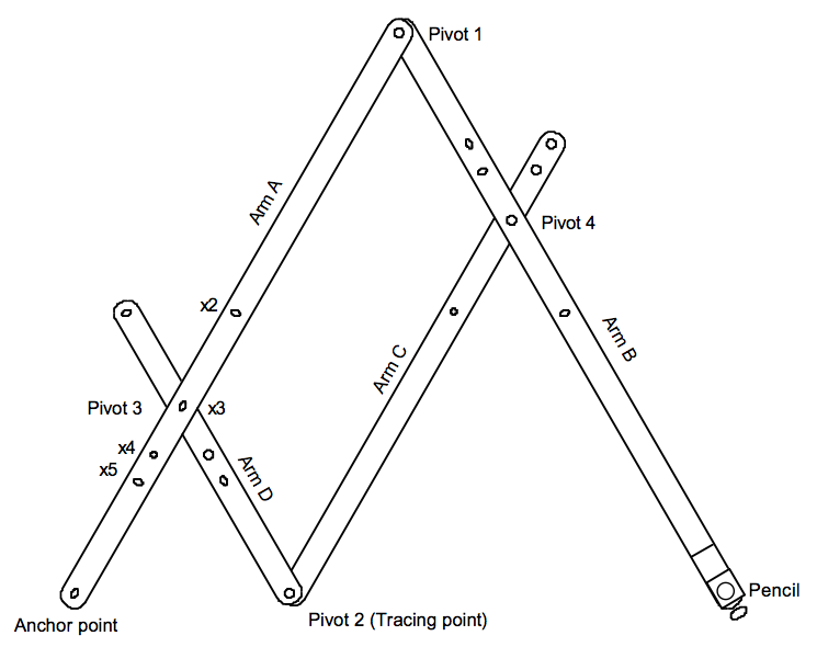
Peter S Articles How To Build A Pantograph
The mechanics of the device serve to keep that ratio constant as the mechanism is rotated expanded andor contracted.

. The specially developed hardware-in-the-loop test facility is unique in the world and makes it possible to emulate the interaction between the pantograph and simulated overhead contact line in real time. Therefore this project is aimed at developing a Pantograph mechanism which can be used to magnify the smaller shapes on the sheet metals. Shows a basic panto graph.
Mathrm min y F x X_ max- X_ minmax abs 17circ -theta T 10. The 3 2 3 2 cos 90 sin cos cos 90 sin cos x L b L N L b N L γθ θ α γθ θ α. Optimization design requirement for pantograph limit height is 3000mm and the time of rising pantograph controls within 6s.
It is often suitable to connect the definition of the dynamic system to a CAD-tool where it is easy to define geometry calculate mass and inertia position of joints and loads etc. Pantographs in operation are entirely or partially charged to build electric contacts. Each CAD and any associated text image or data is in no way sponsored by or affiliated with any company organization or real-world item product or good it may purport to portray.
Now draw a rectangle or circle with a simple notch or a cove in it. Good luck John N. Three-dimensional CAD models are also suitable for visualisation of the design for investigation of aerodynamic forces animation of the dynamic behaviour etc.
The aerodynamic uplift force model of pantograph was established and the method to calculate the aerodynamic uplift force was derived. Pantographs are a special devices mounted on electric trains to collect current from one or several contact wires. The automated analysis of this system helps prevent incidents of catenary tearing and also allows predictive maintenance of carbon slide plates.
Distance from the fixed point to the drawing point distance from the fixed point to the tracing point. Now you have to choose a stylus that will at least enter the form in the model. And it replaces all the drawing tools on the work table.
The Pantograph Condition Monitoring System provides automatic analysis of the condition of pantograph heads on railway rolling stock. Pantograph measurements and the evaluation of the catenary condition can be made with regular railway engines equipped with measurement systems during normal operation. They consist of a pantograph head frame base and drive system and their geometrical shape is variable.
Then when you roll the quilt back on the frame make sure your needle is in the down position so you dont lose your spot. According to the requirements of the above-mentioned pantograph structural parameters the objective optimization function of the target bow balance bar according to the pantograph trajectory can be designed as follows. Siemens Mobility performs the entire development process including design construction calculation simulation prototype building and production in Austria.
Measurements should include values such as vertical contact force vertical acceleration and sideway position calculation from contact forces. The scale factor is the ratio. Roll the machine down so its between the two dashed lines at the bottom of the pantograph design.
By stitching up to the topmost dashed line youre creating the space between the pantograph rows. According to En 50317-2012 standard the calculation of arcing rate is related to arcing time and current it is necessary to measure the current of pantograph. Then as you.
The graduation of the rods for the adjustment pivot holes is carried out. Cut out of 18-inch oak walnut or beech four rods 58 inch wide and 19 inches long. Smooth them well all over and make marks near the ends of each exactly 18 inches apart.
Nov 12 2016 2. Such could be accomplished with any stylus and any cutter merely adapting the pantograph ratio to get the size desired. WHAT IS a PANTOGRAPH A pantograph is basically a square with pivoted comers if holes are drilled in its arms it could be used for enlarging or reducing drawings or artworks.
The following is the simulation image of rising pantographs height. The system operates at speeds of up to 140 kmh in most weather. So the structure topology of the pantograph dynamic comprehensive detection system based on edge calculation for straddle type monorail vehicle is shown in Fig.
Note the pivot points. Calculated for different situations. The Computer-Aided Design CAD files and all associated content posted to this website are created uploaded managed and owned by third-party users.

Pantograph Model And Geometry Of The Frame Download Scientific Diagram

Panto Graph Mechanism Design Grabcad Tutorials
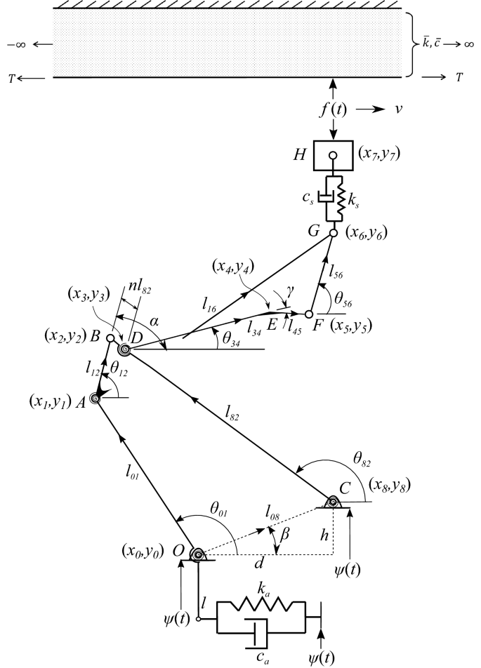
Dynamic Interaction Between Multiple Pantographs Sliding On An Overhead Conductor Wire A Multibody And Wave Based Approach Springerlink
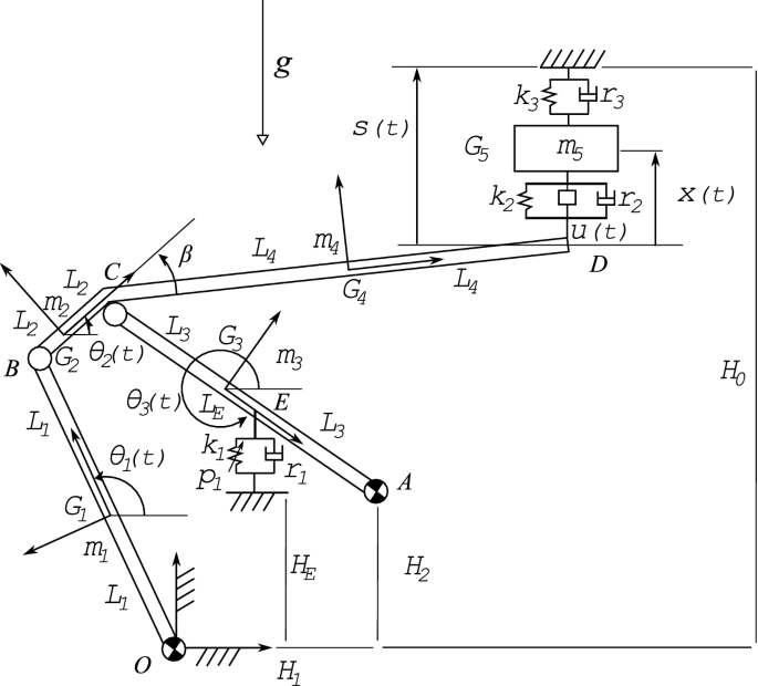
Multibody Modeling And Nonlinear Control Of The Pantograph Catenary System Springerlink
Design And Control Of A Pantograph Robot Northwestern Mechatronics Wiki
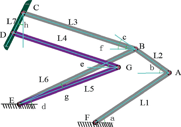
Parameter Optimization Of Pantograph Structure Based On Multi Objective Genetic Algorithm Springerlink
Design And Control Of A Pantograph Robot Northwestern Mechatronics Wiki

Panto Graph Mechanism Design Grabcad Tutorials

Panto Graph Mechanism Design Grabcad Tutorials

Pantograph Lifting Platform Slaughtering Machines

Panto Graph Mechanism Design Grabcad Tutorials

Pantograph And Catenary System Download Scientific Diagram
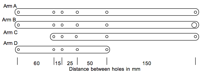
Peter S Articles How To Build A Pantograph

Graphical Representation Of A Pantograph Model A Two Dimensional Download Scientific Diagram

Technology Use In Math Construction Of Pantograph On Sketchpad And Mathematics

Pantograph Configuration Download Scientific Diagram

A Pantograph Of Two Masses Lateral View Download Scientific Diagram

0 Response to "pantograph design calculation"
Post a Comment